
Building a custom telescope mount with harmonic drives and ESP32
How I went from buying a €200 tracker to building a custom telescope mount with harmonic drives, ESP32, and way more engineering than necessary
The Spark
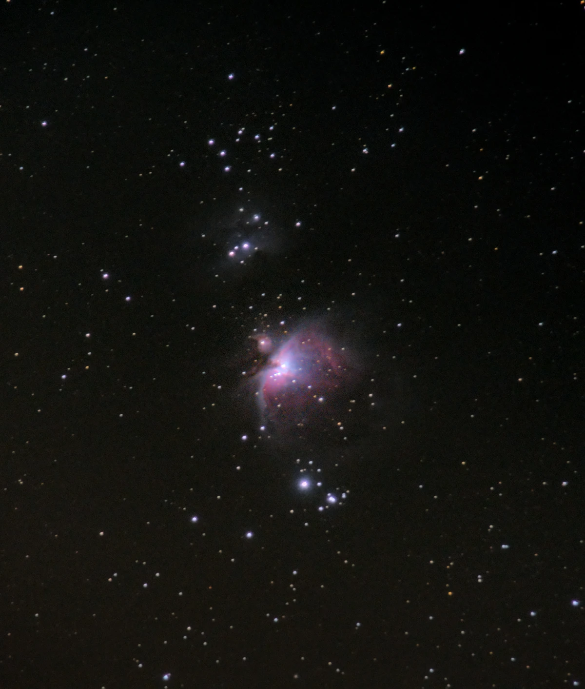
A few years back, I developed an interest in astrophotography thanks to YouTubers like Nebula Photos. Armed with an OM System OM-5 and a 15-140mm Olympus lens, I managed some decent shots of the Orion Nebula from a tripod by taking 300 pictures with a 2-second exposure time and stacking them in Siril.
Knowing I could achieve better results with tracking, I bought a Move Shoot Move tracker for around €200. It delivered longer exposures, but finding targets and achieving proper polar alignment remained challenging. I spent countless hours researching proper telescope mounts with GOTO and tracking capabilities, coming close to pulling the trigger on units ranging from €1,200 to €4,000. For a hobby I was still exploring, that investment always felt like a leap too far.
The PCB Awakening
Late 2024 I randomly came across this YouTube video about custom PCB design in my feed, and I was hooked immediately.
With a decent collection of microcontroller boards, the idea of ditching messy breadboards for clean, custom, affordable PCBs was revelatory. My first project replaced my home thermostat with an ESP32-based design with e-paper display, interlocking finger patterns for the original carbon rubber dome switches and space for a Bosch BME680 sensor breakout.
After completing that project, I revisited the telescope mount idea - this time armed with newfound PCB design skills. The question emerged: "How hard can it be?"
Down the Research Rabbit Hole
The plan crystallized around harmonic drives (strain wave gears) - the favorite of modern telescope mounts for their excellent performance in compact packages. The concept seemed straightforward: motor, microcontroller, optional gearing, and a strain wave gear, all housed in a sturdy enclosure.
I divided my time between scouring AliExpress for components and studying existing DIY builds. AliExpress proved to have the worst search functionality in e-commerce history. Google's site:aliexpress.com became my most reliable tool. Hours were spent analyzing technical drawings of every available harmonic drive, searching for workable options and trying to not lose my mind in the myriad of near-identical items from multiple vendors.
Some other DIY projects provided me with invaluable information:
- HEMY - Harmonic drive equatorial mount
- HrEM - Harmonic reduction equatorial mount
- DHEM - Dual harmonic equatorial mount
- DIY EQ Mount V2 - Comprehensive build guide
Soon I was looking into the workings of stepper motors, BLDC motors, Field Oriented Control (FOC), and various open source FOC implementations like SimpleFOC.
Design Decisions
Honestly, this build didn't require a custom PCB. A FYSETC E4 board or even a breadboarded ESP32 would have worked. But I wanted to create something beautiful from scratch, achieving that "I made this" feeling. The housing, however, absolutely needed to be sturdy and custom-designed.
I started learning FreeCAD alongside KiCad, producing about eight throwaway housing designs before the concept solidified.
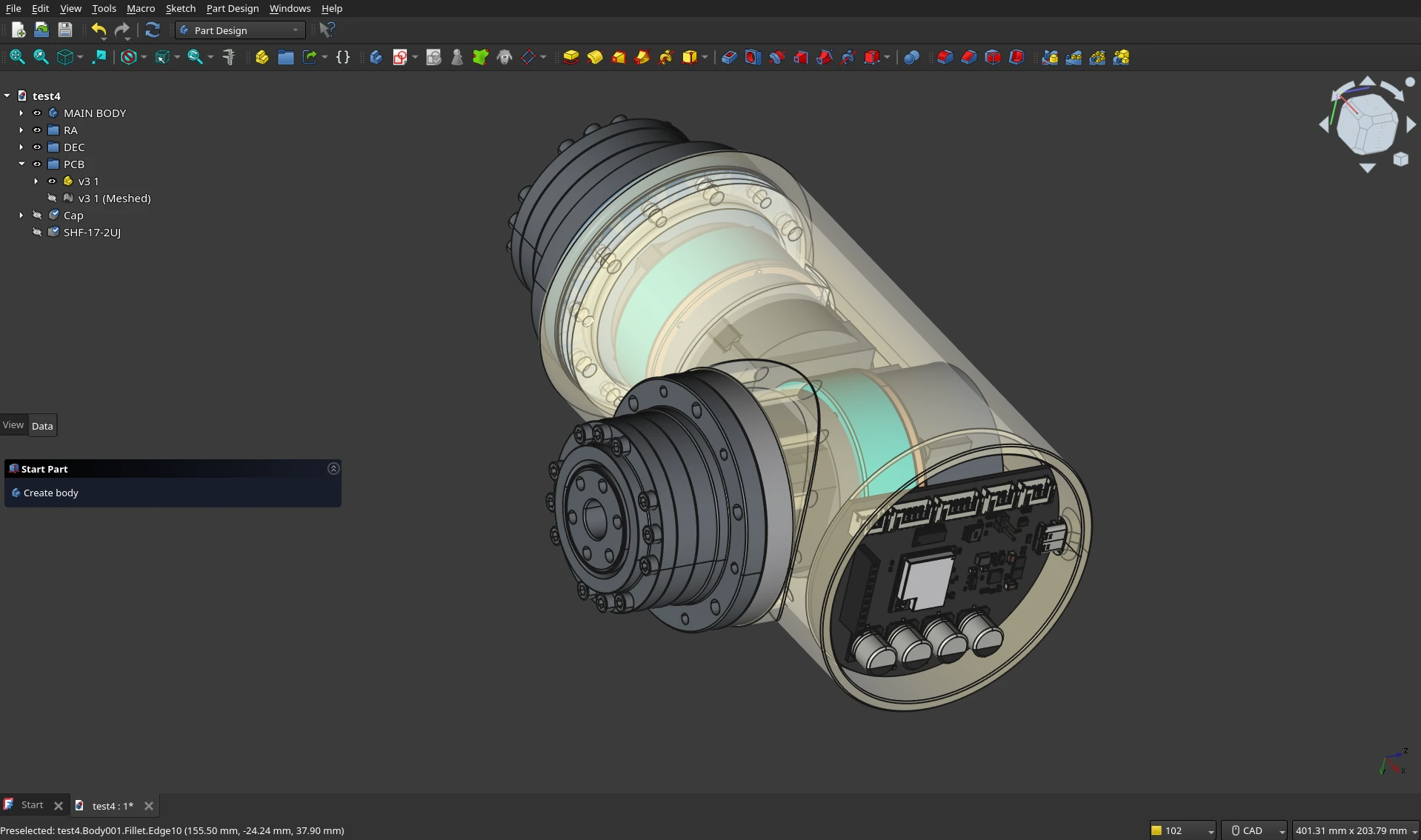 Housing design iterations in FreeCAD - multiple attempts to get the geometry right
The Architecture
- RA Axis: 42AIM15 Servo motor with Type 17 harmonic drive (100:1 reduction)
- DEC Axis: MKS Servo042D stepper with Type 14 harmonic drive (100:1 reduction)
- Mounting: Arca Swiss plate (compatible with existing Move Shoot Move wedge)
- Operation: GEM or ALTAZ modes
- Microcontroller: ESP32-S3
- Power: USB-C power delivery up to 24V/4A
- Motor driving: step/dir/en ports via the ULN2003 + MODBUS and CANBUS ports
- Extra: Leftover GPIO pins broken out for future use
The 42AIM15 provides 32,768 steps per revolution, configurable to 65,536 steps with 2x oversampling. The MKS Servo042D supports microstepping up to 1/256. Both motors were chosen for their integrated drivers, dramatically simplifying PCB design. With FOC and microstepping, other builds demonstrated decent tracking accuracy without intermediate reduction. Via CANBUS I can control the microstepping regime of the stepper motor. During slews I set the microstepping to 128 from 256, allowing a higher slew speed in degrees / second without putting too much load on the microprocessor.
The PCB Design
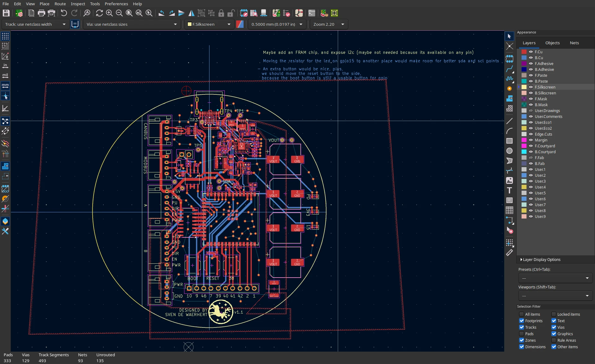 PCB layout in KiCad showing the semi-circular form factor and component placement
The PCB takes a semi-circular form factor, designed to fit snugly within the housing. This unique shape and placement didn't significantly increase the size of the mount, which I already felt was becoming quite beefy. I used an ESP32-S3 Microcontroller without the PCB antenna, so I could fit the module anywhere on the board. The first traces I routed were power and the USB differential pair. I managed to place the microcontroller in such a way that the differential pair goes in a straight line.
Power is available through USB-C thanks to the AP33772 IC which negotiates power via the CC pins on the USB-C connector. Power banks supporting USB PD 3.0 and able to deliver 12V are excellent for making this entire setup portable. Major props to the guys from CentyLab for their PicoPD schematics and PCB designs using the AP33772. This was a big inspiration for laying out my components. The output trace is very wide to support 24V* and also has 4 large capacitors. In hindsight, those caps were maybe a bit overkill because the motors for this usecase hardly produce any sudden power peaks, and a good USB PD power supply would probably already have a decent enough amount of capacitance.
Correction*: The wide output trace is for current capacity, not because it’s 24 V; voltage primarily sets spacing. Hat tip to the astute reader.
During my research I noticed a lot of integrated motors with CANBUS/MODBUS features, so I added functionality for that as well. The remaining GPIO pins of the ESP32 I simply routed somewhere nearer to the edge of the board so they can be used for other purposes in the future.
Some thought has also gone into choosing the right PCB mounted connectors. I settled on the JST PH series for their compactness and their ability to carry 2A per pin. Matt Millman's Common JST Connector Types was a great resource for making the final selection.
The First PCB Mistake
Initially my design was around the AP33772S IC. A last-minute component substitution at JLCPCB - changing the originally specified IC due to stock issues - should have triggered a complete pin compatibility review. Impatience won, and I ordered anyway, replacing the AP33772S with the AP33772.
The result: I2C communication was impossible due to NO-CONNECT pins erroneously tied to ground, and manually getting the VBUS voltage to 24V using an external PD trigger board caused a sudden tiny hole to appear on the chip package, followed by blue smoke. Lesson learned. Version 2 underwent exhaustive verification, and worked flawlessly when it arrived. I also included significantly more test points throughout the board, whch is a practice I'm going to keep going forward. The version 1 boards still work for controlling the mount, but they lack the intergated power delivery.
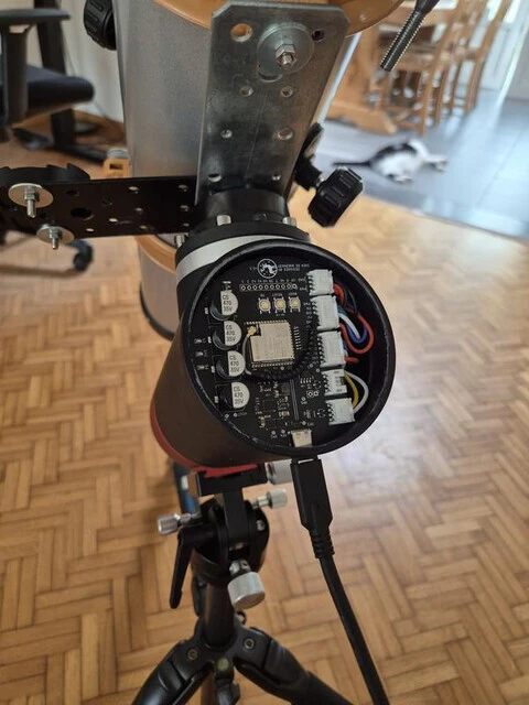
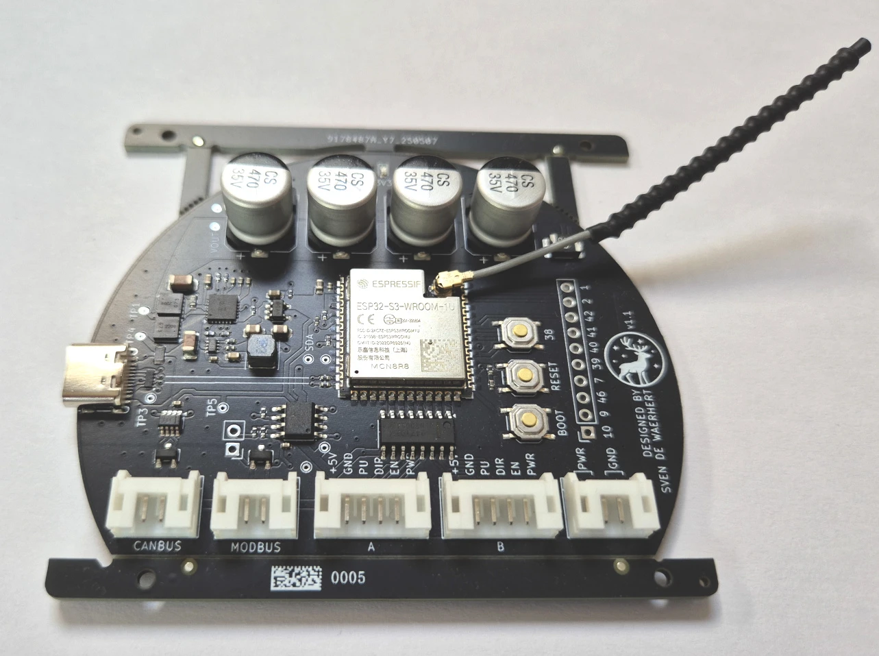 Version 2 of the custom PCB
OnStepX Integration
OnStepX is telescope mount firmware supporting multiple microcontroller platforms, originally developed by Howard Dutton to save his mount from obsolescence. It has since grown into a major open source project with substantial community support.
Without OnStepX, DIY telescope mounts like this wouldn't be feasible for many builders. The ESP32 WiFi support became my preferred communication method, though initial testing revealed WiFi instability during slewing operations. Not surprising once you understand that slewing to a target significantly increases the number of pulses per second sent to the motors, and everything became just too much to handle for our little ESP32.
Two changes resolved the stability issues:
- Reducing slew rates or increasing step sizes with lower microstep divisions (configurable on-the-fly through OnStepX hooks in the generic motor class)
- Configuring the device as a WiFi client rather than access point
Apart from adding a custom pin layout file and some code to lower the microstep subdivisions during slewing, OnStepX really just worked out of the box.
Manufacturing and Assembly
All manufacturing was handled by JLCPCB - both PCB fabrication and CNC machining. Sending CNC production files without 3D printing prototypes first was a calculated gamble that paid off; everything fit (almost) perfectly upon arrival.
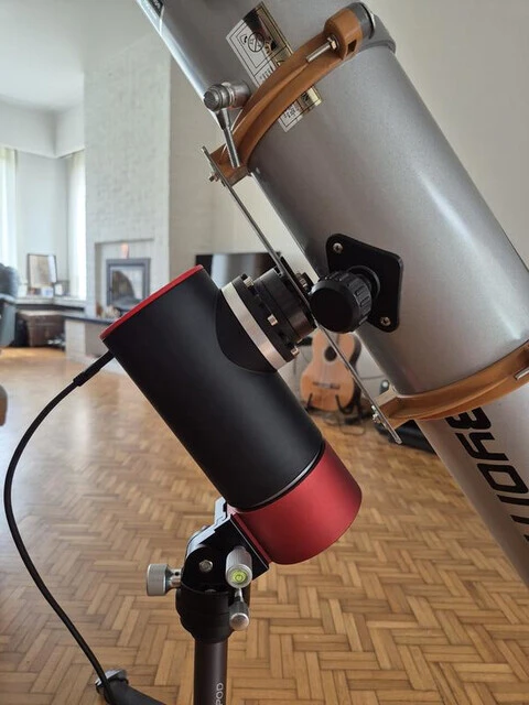 Mount fully assembled. Yes, those are 5 euro rainwater pipe clamps holding the telescope
One minor adjustment was required: the red cap at the RA axis rubbed against the harmonic drive. The oversight occurred because I modeled the cup interior without accounting for the harmonic drive mounting screws. I used a simple spacer to fix the problem. I'm very impressed with the manufacturing quality of the components. To assemble everything I just needed to thread the holes with some M3 or M4 taps and bolt everything together. I opted for manual tapping to save on manufacturing cost.
Real-World Performance
Countless nights were spent mastering polar alignment, scope setup, and navigating the quirks of KStars, Ekos, and INDI server. The first cloudless nights usually ended in frustration: between polar alignment, WiFi issues, indi server issues, camera issues, slipping motor couplings, and software configuration, dawn would arrive before I captured a single frame. At one point, I celebrated achieving 0.1 arcsecond precision! - only to discover PHD2 was configured with incorrect focal length settings and reported skewed results.
The best verified precision achieved so far is 1-2 arcseconds observed with PHD2, more than adequate for 30-second exposures with a 600mm focal length Sigma lens. I continue using my camera in interval mode, ensuring the signal is somewhere in the middle of the histogram. ISO 3200 usually, with sensor stabilization and noise suppression disabled. Stacking is performed in Siril, though multi-night stacking remains a goal requiring significant planning, luck, and consistency.
 The completed mount setup
The Economics
Total project cost reached approximately €1,700, including reusable tools like thread taps, various M3/M4/M5 hardware and JST Connector tools. Sometimes bulk purchases or shipping minimums inflated costs. I also bought 2x unused MS6010v3 motors for experimenting/evaluating for a potential future super compact build. And the extra cost of the PCB revision ofcourse.
Calculating single-unit costs yields approximately €800, with potential for reduction in larger quantities. Compared to commercial GOTO mounts in the €1,200-€4,000 range, the economics are competitive - but economics was never the primary driver.
Detailed Cost Breakdown
| Component | Category | Total Cost (€) | Single Unit (€) |
|---|---|---|---|
| Cuttin Tap 1/4-20 UNC | Tools | 2.89 | 1 |
| Cutting Tap Form D - UNC 3/8 x 16 | Tools | 12.88 | 1 |
| 220 pieces M5 screw set | Tools | 10.59 | 1 |
| 440 pieces M4 screw set | Tools | 13.21 | 1 |
| 440 pieces M3 screw set | Tools | 9.14 | 1 |
| Metric tap set MetricssMann M53250-B | Tools | 27.38 | 1 |
| PEBA JST PH 2.0 Crimping set | Tools | 31.11 | 1 |
| Tools Subtotal | 107.2 | ||
| MKS SERVO42D NEMA17 Closed Loop Stepper Motor | Mount | 73.2 | 36.6 |
| Harmonic drive 2x | Mount | 144.44 | 144 |
| Import tax harmonic drive 2x | Mount | 30.24 | 15 |
| Servo motor 2x | Mount | 216.46 | 151.7 |
| Import tax servo motor x2 | Mount | 86.94 | 43 |
| MS6010v3 (2x) | Research | 216.94 | |
| Import tax MS6010v3 (2x) | Research | 57.05 | |
| CNC parts | Mount | 215.76 | 215.76 |
| Import tax CNC | Mount | 58.04 | 58.04 |
| PCB (5x) | Mount | 178.74 | |
| Import tax PCB | Mount | 33.54 | |
| PCB2 (5x) | Mount | 178.74 | 42.46 |
| Import tax PCB2 | Mount | 33.54 | 6 |
| Extra Harmonic wave generator 8mm | Mount | 44.59 | 44.59 |
| Import customs duty harmonic wave generator | Mount | 36 | 36 |
| Total Project Cost | 1711.42 | 800.15 |
Single unit costs represent what one mount would cost without bulk purchases, shipping minimums, and reusable tools.
Anyway
It was totally worth it.
The failed Version 1 PCB taught me never to skip verification steps, regardless my occasional impatience. OnStepX opened up the world of equatorial mount operation and just the joy of watching that thing slew across the sky. FreeCAD modeling skills improved dramatically through multiple housing iterations. I will probably spend more attention to documenting during future builds: writing down thoughts along the way and taking better pictures/screenshots/recordings.
Sure, I spent about as much as a commercially available mount, but I gained so much more. Plus I have a freaking mount that tracks stars!
That feeling when you point at a nebula, watch it track perfectly, and know (almost) exactly how everything works, cause you built it. ✨
 Andromeda Galaxy, September 2025 - Shot with OM System OM-1 and Sigma 150-600mm
Image Gallery
Continue reading
Building a custom ESP32 thermostat
A guided tour through the code of a battery-powered ESP32 thermostat with e-paper display, deep sleep, and remote control
1.5 Years of Talking to Claude
An analysis of 888 conversations with Claude over 18 months. Perform your own analysis 100% offline.
Nearby peer discovery without GPS using environmental fingerprints
I propose a peer discovery technique to detect nearby devices by comparing similarity in their observed environments, such as WiFi or Bluetooth networks. Using locality-sensitive hashing and private set intersection, peers can compare their environments without disclosing the full details. With sufficient similarity between environments, peers can conclude they are near each other.